Table of Contents
June 2026
Various work:
- the telescope started to oscillate in the past several weeks, evident in the Planewave tracking plots. We ran a quick tuning, but no change. We ran a thorough tuning (couple hours), also no change, but upon rebooting pwi1m computer, problem seems to have gone away. Consulting Planewave (Josh Persson), this is not expected, so unclear what was/is going on!
- we installed a new stage for the iodine cell; previous stage was damaged and shipped to Thorlabs for repair. We used the bright LED source through a 10-micron fiber in the cal channel to project the beam through the system. We attached a card to front of iodine cell with a cross in the middle, and attempted to position the cell (in height) to center the beam on the spot; subsequently, determined stage postion to the the same in left-right motion. Connected the cell heaters/sensors to the TC300; reset to dual channel operation and PT100 sensors (black and white wires).
- using 10 micron fiber with calibration source, investigated cal channel image quality, and image quality through iodine cell. Found that cal channel image quality was very poor. Attempted adjustment of both collimator and camera lenses and was unable to make any significant improvements. NOTE; we don't really care about image quality in cal channel because it is a diffuse source for calibration observations, but we wanted to get decent images to determine whether they are changed through iodine cell. Called Edmund Scientific, who advised that the doublets should be oriented with curved sides towards the image source and output image, backwards from how they were installed, so reversed the optics in their cells and reinstalled. Images better, but still poor. Did not attempt to improve the images, but determined that adding iodine cell only made minor changes to the image! So cautiously optimistic.
- redetermined calibration spot and hole positions. Focussed guide camera.
- connected the QHY600 USB directly to the computer, rather than running through the Wanderer, in an attempt to cure the disconnects we have been getting
- inspected Shelyak calibration source due to no LED light and determined that indeed, no LEDs appear to be coming on inside the unit. Emailed Shelyak.
- took pixel flats with liquid cooled QHY600. This was achieved using a LED penlight wrapped in some bubble wrap and inserted into the upper light feed without moving anything in the spectrograph. Took 101 .0005s exposures
- checked lower dome, which wouldn't open, even though it hasn't been used since Ben last looked at it and claimed it was fixed and working. Perhaps there is some thermal effect. When it gets in this tightly wrapped state, a screwdriver can be inserted in the right side to push the spring loaded catch down, after which you can pull on the cable/push shutter to loosen the system, after which it worked. Experimented with software for safe use of lower dome shutter. When it does fail, it always seems to be in that it won't open, but closes fine, so perhaps the episodic failures are not a show stopper (Bill suggests that running the motor and having the couple slip won't damage the coupler). Otherwise, software seemed to work ok, although there was one instance where, after opening, software thought is was closed, so automatic closing didn't proceed as it should have. Probably should triple-check this! Implemented some new supported actions in dome driver to allow for easier testing by setting open/close time for both shutters to a shorter value so that they don't have to go all of the way.
- at end of run, inspected calibration frames and see apparent drop in flux from previous week, especially in flats, but also in ThAr, with drop in both cal channel and direct channel. Lots of investigation followed, determined that fluxes can change with reseating of fiber in cal source, although still couldn't recover previous fluxes. Did fiber inspection and cleaning using APOGEE fiber microscope and cleaning device (with assistance from Jimmy Davidson), found some of the fibers pretty dirty, but didn't make dramatic changes in flux. Flipped the bifurcated fibers as one test. Direct fiber still much brighter in flats, but not nearly so much in ThAr? Final tests suggest significant change in flats but less in ThAr? Not clear what is going on, but maybe the illumination in the cal source is sufficiently non-uniform to make small changes in fiber placement significant, especially for quartz lamp? But swapping bifurcated fiber didn't seem to change the relative brightness dramatically. Maybe some issues with quartz lamp?
April 2026
A new iodine cell was installed.
We implemented a shutter in the direct calibration channel.
We got the repaired liquid cooled CCD back from QHY and installed it, along with the TCube Edge chiller.
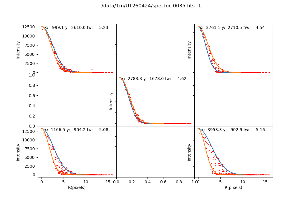
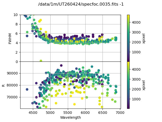
When revisiting spectrograph focus, the Esatto focuser would intermittently time out. As a result, it's uncertain whether the reported focus position is repeatable, e.g., after homing the focuser. Given potential repeatability issues, the focuser was just moved until acceptable images were reached, which is at a currently reported value of 398000. After settling on that, the Esattor focuser was powered off through the Wanderer PowerBox to remove the light source. A final image at this focus is UT260424/specfoc.0035.fits. 2D profiles for 5 ThAr lines, and 1D FWHM are as follows:
November 2025
Enclosure box installed 11/18-29. Required taking ferrule out to run through box, so location of traces, etc. changed. Installed 4 temperature sensors inside the box. Cleaned up room and put spare parts on shelf and in drawers. Installed pass-thrus for cables on FPUs. Connected big dome fan to outlet #10.
Spectrograph refocussed. Images look more circular in middle of chip at lower focus values, but extracted images show more variation in resolution at the lower values.
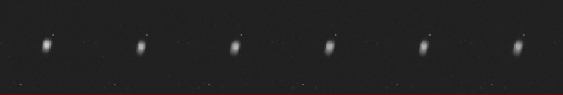
Images from 433000 (left) to 438000 (right) in steps of 1000 near center of chip:
Extracted FWHM/Resolution from the same sequence:
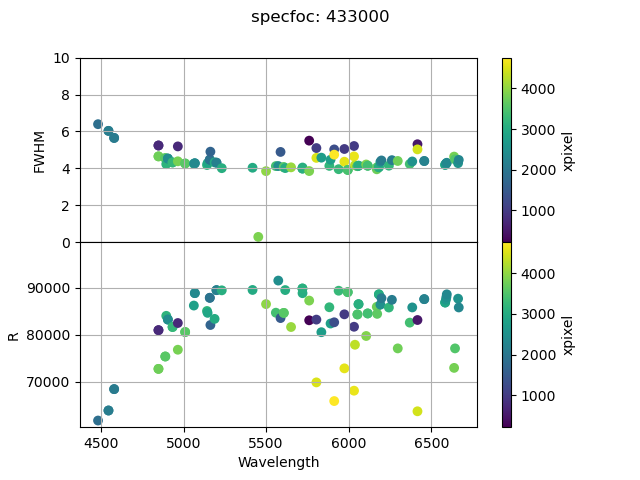 | 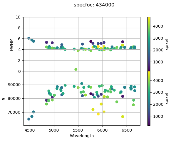 | 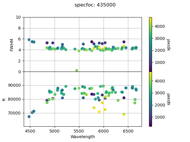 | 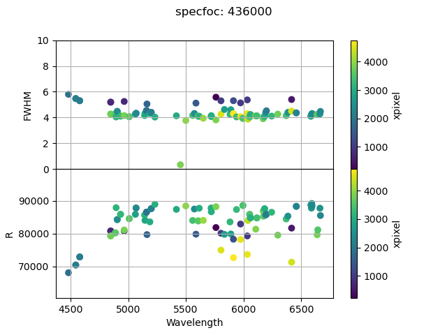 | 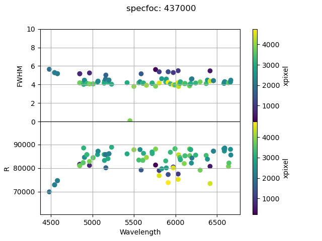 | 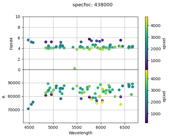 |
Not overly satisfying, but adopted 437000.
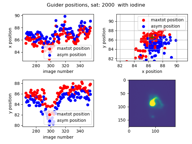
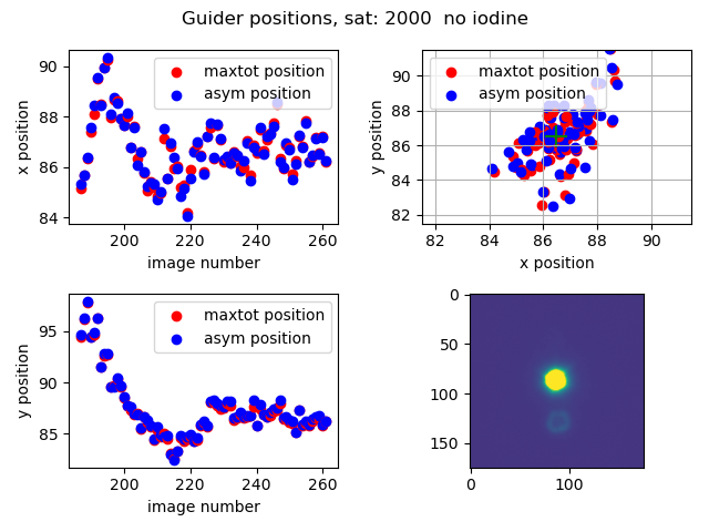
Guiding tests
Star off fiber, not saturated

Throughput
Spectrograph throughput at 5560-5570
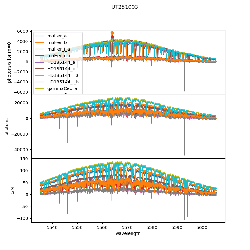
For each science spectrum, the flux is extracted in each order using a boxcar extraction, and a wavelength solution from a ThAr frame is attached. We then determine the maximum flux between 5560 and 5570 Angstrom. We convert this to electrons per second for a star with m=0 using the exposure time, V magnitude of the star, and gain; we'll loosely call this throughput. This is plotted in the top panel of the following plot (other panels are not relevant here, but are the observed flux in the exposure and predicted S/N based on this):

Clearly, there is some variation in the throughput, which is expected because of variations in transparency and also variations in seeing, leading to different fiber losses at the focal plane. However, the exposures with iodine (+ symbols) are clearly significantly lower than those without iodine (squares) by a factor of roughly 2-3 (we've been using 2.5x the exposure time for iodine, and you can see in the middle panel that this roughly brings observed fluxes to be the same); i.e., iodine throughput is ~40% of the non-iodine throughput.
The horizontal lines represent throughput achieved at the Tenerife SONG node for several different stars (median of many observations), I believe through iodinec cell, from some paper….
Stellar profiles with and without iodine
To understand the source, we observed a star on the guide camera (off of the fiber hole) with and without iodine cell, and plot the cumulative counts in successive circular apertures. Top plot shows the two cumulative flux curves, and bottom plot the ratio.
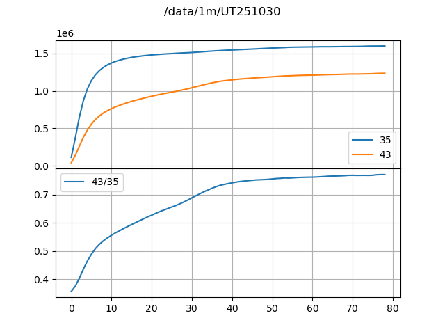

The profile with the iodine cell is both less concentrated and also never achieves the same flux as the profile without the iodine cell. Of course, the comparison assumes that the transparency is the same for both exposures. The total flux suggests about a 20% loss of flux. Comparison of the total flux ignores the fact that some light is really absorbed by the iodine, but the response of the detector is broad and probably peaks in the red, so the expectation is that this may not be expected to be a lot. Some total light loss is expected from the uncoated interior surfaces in the iodine cell. Paul Butler estimated 4-6% at each surface, so 10-12% overall, while we may be seeing 20%.
The pixel scale of the guide camera is about 0.16 arcsec/pixel, so the hole to the fiber corresponds to about a 5.5 pixel radius. At this radius, the ratio is about 50%, perhaps a little bit higher. This is close, but not equal, to the 40% measuredabove from the spectra. Of the 50% loss, perhaps a bit less than half comes from the total throughput, while the rest comes from the degradation in image quality.
Paul also mentioned that the ends of the cell are likely to be bowed a bit, but we don't know how much image degradation this might lead to.
Image quality with iodine cell
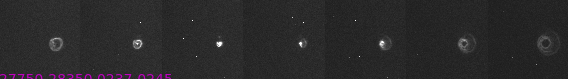
The following images shows a focus sweep of a star with the iodine cell in place (at two contrasts). Compared with similar images without the iodine cell, the core is blurrier, but there is also some very asymmetrical light outside of the core of the image.
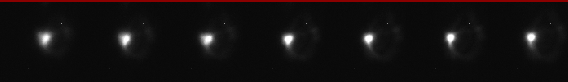
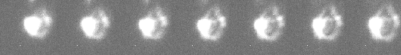
The following images show coarse focus run with and without iodine cell in place. Aberration is clearly present with the iodine cell.

Cal channel iodine/clear flats
To look at the overall throughput of the iodine cell in a different way, we looked at flat fields taken with and without the iodine cell. The ratio of these is shown in the following plot.

This suggests an overall throughput of 75% or less, under the assumption that the same amount of calibration light is incident on the fiber; our calibration spot is 200 microns in size for a 50 micron hole, and we have adjusted the iodine cell so that the hole is in almost the same location when the cell is in place, but it is not exact, although we think it is close enough that roughly the same amount of flux should be going down the hole.
Interestingly, the iodine data here was taken after the iodine cell heaters had been turned off for 12 hours, with the cell around 13 C, but iodine absorption is still present!
October 2025
Fiber spool 241586 (the better of the two) was pulled through the conduit.
Using fiber 2 for the science fiber, as it had consistently highest measured throughput. Absolute and relative throughputs with cal lamps were similar to those measured using the fibers in the lab.
In the focal plane, fiber 2 is the lowest, with fiber 3 above it and fiber 1 at the highest row. At the maximal separation between the different fibers, fibers 3 and 1 overlap in the redder orders. The ferrule was rotated (to about 45 degrees) to avoid this. Without a shutter in the direct calibration feed, the direct calibration fiber was left unconnected.
First light on 251002 obtained spectra! However, images with iodine cell appeared poor and resulting spectra had much lower throughput than without iodine, perhaps due to combination of image quality and guiding on poor images.
Modifications made to change guiding algorithm to ignore saturated pixels to allow for longer exposure times to average out the seeing.
251003 observed several stars. Throughput without iodine doesn't look too bad when compared with Tenerife measurements, a little lower, but not dramatically so. Throughput with iodine still looks poor. In plot below, three dots are from SONG paper with photon rates from these three stars, claimed to be median of many exposures. Repeatability of multiple observations of multiple stars is encouraging from the point of view of guiding.
251006 repeated observations of several stars.